はじめまして、フリーランスのますみです!
『一人一人が自立・共存・革新している「クリエイターエコノミー」を創る。』というビジョンに向けて活動しています。

micro:bitで操作をすると、シリアル通信でProcessingとやりとりをするシステムを作る記事です。具体的には、マイクロビットでボタンが押されたら、Processingの画面でオブジェクトが表示されるようにしていきます。
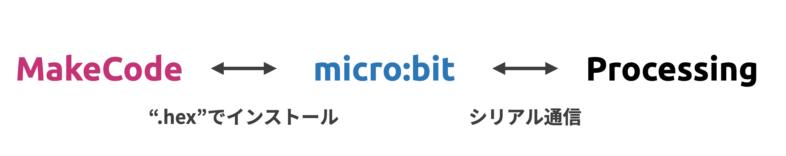
全体のシステム
以下のように、MakeCodeというMicrosoftのソフトで、micro:bitのコーディングを行い.hexファイル形式で、micro:bit本体にインストールします。そして、micro:bitからポートを用いたシリアル通信でProcessingに信号を送ります。
この記事では、信号を受信したProcessingでデジタルアートを描きたいと思います。
手順
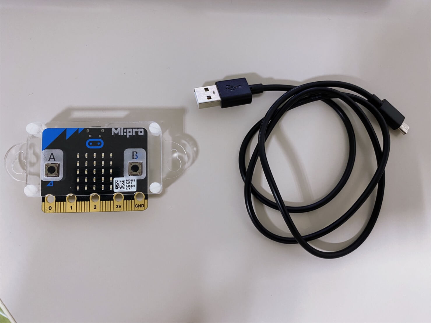
1. micro:bitの準備
まずは、micro:bitとマイクロUSBケーブルを用意し、パソコンと接続します。
2. micro:bitのコーディング
2-a. 新しいプロジェクトの作成
まずMakeCodeのmicro:bitのウェブサイト(こちら)にアクセスをして、新しいプロジェクトを作成しましょう。

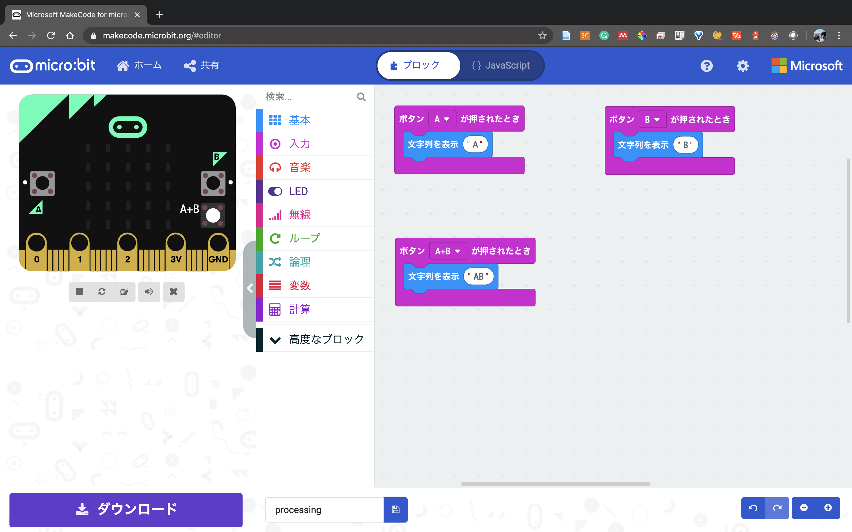
2-a. 接続テスト
まずボタンを押したら、micro:bitの画面に文字が表示されるか実験してみましょう。
以下のようにプログラミングをしてましょう。
それぞれ基本と入力のブロックを使っています。
プログラムができたら、ダウンロードをして、.hexファイルを出力しましょう。
出力ができたら、以下のように.hexファイルをMICROBITへドラッグ&ドロップして、コピーします。

この状態で実行して、以下のように文字が表示されれば、接続テスト完了です。
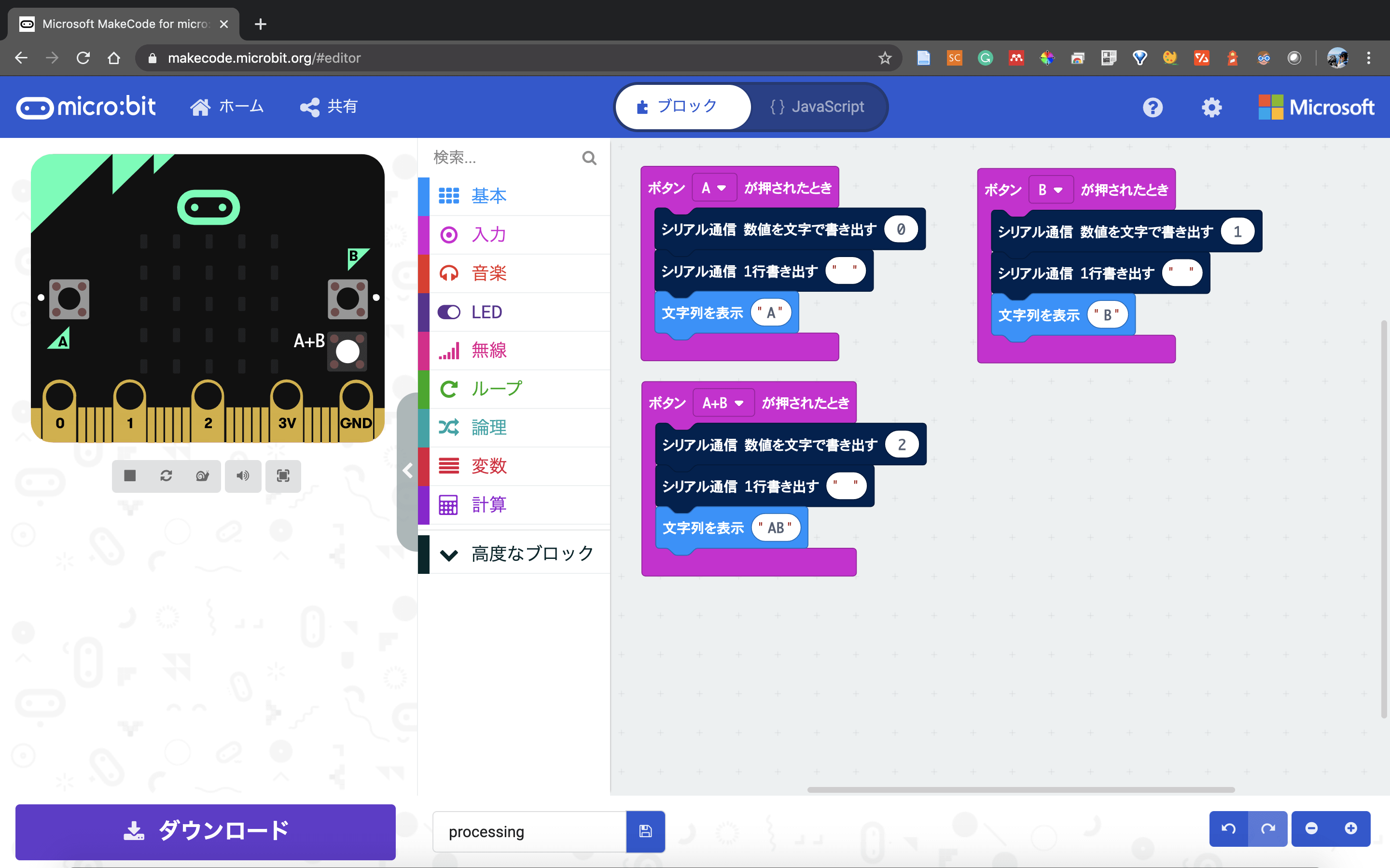
2-b. シリアル通信のプログラム
続いて、シリアル通信のプログラムを追加していきます。以下のようんブロックを追加してみましょう。シリアル通信ブロックは、高度なブロック > シリアル通信の中にあります。
これで再びダウンロードをして、MICROBITへコピーしたら、microbitのプログラミングは完了です。
3. Processingのコーディング
3-a. Processingのダウンロード
Processingのダウンロードサイト(こちら)よりダウンロードしましょう。
ダウンロードができたら、アプリケーションを起動しましょう。
3-b. シリアル通信受信のコーディング
起動ができたら、以下のようにコーディングを行なっていきます。下半分は円を綺麗に生成するためのスクリプトなため、完全に理解はできなくても大丈夫です。
3つの重要な箇所だけソースコードの後に解説します。
import processing.serial.*;
Serial microbit;
int _num = 10;
Circle[] _circleArr = {};
void setup(){ size(640, 480); background(255); smooth(); strokeWeight(1); fill(150, 50); String portName = Serial.list()[1]; println(portName); microbit = new Serial(this, portName, 115200); microbit.clear(); microbit.bufferUntil(10);
}
void draw(){ background(255); for (int i=0; i<_circleArr.length; i++) { Circle thisCirc = _circleArr[i]; thisCirc.updateMe(); }
}
void serialEvent(Serial microbit){ String str = microbit.readStringUntil('\n'); str = trim(str); int[] str_split = int(split(str, '\n')); println(str_split[0]); if (str_split[0] == 0){ println("red"); drawCircles("red"); }else if(str_split[0] == 1){ println("blue"); drawCircles("blue"); }else if(str_split[0] == 2){ println("end processing."); exit(); }else{ println("else"); drawCircles("else"); }
}
void drawCircles(String col_type) { for (int i=0; i<_num; i++) { Circle thisCirc = new Circle(col_type); thisCirc.drawMe(); _circleArr = (Circle[])append(_circleArr, thisCirc); }
}
class Circle { // properties float x, y; float radius; color linecol, fillcol; float alph; float xmove, ymove; Circle (String col_type) { x = random(width); y = random(height); radius = random(100) + 10; if (col_type == "red"){ linecol = color(random(150,255), random(100,150), random(100,150)); fillcol = color(random(150,255), random(100,150), random(100,150)); }else if(col_type == "blue"){ linecol = color(random(100,150), random(100,150), random(150,255)); fillcol = color(random(100,150), random(100,150), random(150,255)); }else{ linecol = color(random(100,255), random(100,255), random(100,255)); fillcol = color(random(100,255), random(100,255), random(100,255)); } alph = random(255); xmove = random(10) - 5; ymove = random(10) - 5; } void drawMe() { noStroke(); fill(fillcol, alph); ellipse(x, y, radius*2, radius*2); stroke(linecol, 150); noFill(); ellipse(x, y, 10, 10); } void updateMe() { x += xmove; y += ymove; if (x > (width+radius)) { x = 0 - radius; } if (x < (0-radius)) { x = width+radius; } if (y > (height+radius)) { y = 0 - radius; } if (y < (0-radius)) { y = height+radius; } for (int i=0; i<_circleArr.length; i++) { Circle otherCirc = _circleArr[i]; if (otherCirc != this) { float dis = dist(x, y, otherCirc.x, otherCirc.y); float overlap = dis - radius - otherCirc.radius; if (overlap < 0) { float midx, midy; if (x < otherCirc.x) { midx = x + (otherCirc.x - x)/2; } else { midx = otherCirc.x + (x - otherCirc.x)/2; } if (y < otherCirc.y) { midy = y + (otherCirc.y - y)/2; } else { midy = otherCirc.y + (y - otherCirc.y)/2; } stroke(0, 100); noFill(); overlap *= -1; ellipse(midx, midy, overlap, overlap); } } } drawMe(); }
}
3-c. 重要箇所の解説
(1) シリアル通信の設定
冒頭のコードで、processingのシリアル通信パッケージをインポートして、micorbitというシリアル型の変数を作成しています。
import processing.serial.*;
Serial microbit;
(2) シリアル通信用のポートの指定
シリアル通信を行うためのポートをSerial.list()から探し、その中で1番目(javaの配列は0始まりなので、正確には2番目)のポートを変数に保持しています。115200は、baudRate(ボーレート)と言われる値(1秒間に何回、デジタルデータを変復調できるかを示す値)を表します。microbit.bufferUntilの10は、line feed(改行)を表します。
void setup(){ size(640, 480); background(255); smooth(); strokeWeight(1); fill(150, 50); // Find Port String portName = Serial.list()[1]; println(portName); microbit = new Serial(this, portName, 115200); microbit.clear(); microbit.bufferUntil(10);
}
(3) 通信の値に応じた処理の実行
改行コードを受信するまでシリアル通信を読み込み、読み込まれたらそのコードをコンソールに表示します。そして、そのコードが0か1か2で場合分けをしています。
0の時(Aが押された時)は、redとコンソールに表示し、暖色系の円を生成します。
1の時(Bが押された時)は、blueと表示し、寒色系の円を生成します。
2の時(A+Bが押された時)は、end processingと表示し、processingを終了します。
void serialEvent(Serial microbit){ String str = microbit.readStringUntil('\n'); str = trim(str); int[] str_split = int(split(str, '\n')); println(str_split[0]); if (str_split[0] == 0){ println("red"); drawCircles("red"); }else if(str_split[0] == 1){ println("blue"); drawCircles("blue"); }else if(str_split[0] == 2){ println("end processing."); exit(); }else{ println("else"); drawCircles("else"); }
}
4. ポートの確認
A. Macの場合
terminalでls -l /dev/tty.*と打ち、ポートを表示しましょう。
この場合、Bluetooth-Incoming-Portではなく、usbmodem14102の方になります。
$ ls -l /dev/tty.*
crw-rw-rw- 0,0 root 30 5 19:40 /dev/tty.Bluetooth-Incoming-Port
crw-rw-rw- 0,8 root 30 5 19:43 /dev/tty.usbmodem14102
B. Windowsの場合
少しだけ環境作りが複雑なため、こちらの記事を参考にしてみてください。
5. 実機テスト
Processingを実行して、microbitでAボタンやBボタンを押してみましょう。
以下のように円が生成されれば、シリアル通信成功です。
その他
サンプルコードもこちらに掲載しておきました。
最後に
いかがだったでしょうか?
この記事を通して、少しでもあなたの困りごとが解決したら嬉しいです^^
おまけ(お知らせ)
エンジニアの仲間(データサイエンティストも含む)を増やしたいため、公式LINEを始めました🎉
「一緒に仕事をしてくれる方」「友だちとして仲良くしてくれる方」は、友だち追加をしていただけますと嬉しいです!(仲良くなった人たちを集めて、「ボードゲーム会」や「ハッカソン」や「もくもく会」もやりたいなと考えています😆)
とはいえ、みなさんにもメリットがないと申し訳ないので、特典を用意しました!
友だち追加後に、アンケートに回答してくれた方へ「エンジニア図鑑(職種20選)」のPDFをお送りします◎